Showing posts with label car. Show all posts
Showing posts with label car. Show all posts
Saturday, October 5, 2013
Car Battery Saver
Prevents the complete discharge of the battery when the door is left open accidentally
I recently forgot to close the door of my car after parking in the garage and I found the battery completely exhausted after the week-end, when I tried to start the engine on Monday morning. This inconvenience prompted me to design a simple circuit, capable of switching-off automatically after a few minutes the inside courtesy lamp, the real culprit for the damage.
 Parts:
R1______________10M 1/4W Resistor
R2______________10K 1/4W Resistor
C1______________47µF 25V Electrolytic Capacitor
IC1____________7555 or TS555CN CMos Timer IC
D1___________1N4148 75V 150mA Diode
Q1____________BD681 100V 4A NPN Darlington Transistor
LP1___________Existing Lamp Bulb, usually 12V 5W
SW1____________SPST Existing Door-Switch
SW2____________SPST Existing Bypass Switch
Circuit operation:
When the door is opened, SW1 closes, the circuit is powered and the lamp is on. C1 starts charging slowly through R1 and when a voltage of 2/3 the supply is reached at pins #2 and #6 of IC1, the internal comparator changes the state of the flip-flop, the voltage at pin #3 falls to zero and the lamp will switch-off. The lamp will remain in the off state as the door is closed and will illuminate only when the door will be opened again. The final result is a three-terminal device in which two terminals are used to connect the circuit in series to the lamp and the existing door-switch. The third terminal is connected to the 12V positive supply.
Notes:
- With the values specified for R1 and C1, the lamp will stay on for about 9 minutes and 30 seconds.
- The time delay can be changed by varying R1 and/or C1 values.
- The circuit can be bypassed by the usually existing switch that allows the interior lamp to illuminate continuously, even when the door is closed: this connection is shown in dotted lines.
- Current drawing when the circuit is off: 150µA.

Sunday, April 7, 2013
50W car audio amplifier schematic
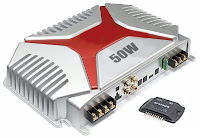 Car power amplifier uses SI1050GL IC as the main amplifier. The output power 50 Watt 8 ohm mono impedance. Up to 25 Volt DC voltage. with source voltage of this amplifier car battery has to work.
Minimum of 12 Volt battery voltage, less than a sound or audio is issued less than the maximum and less good. You can assemble this circuit amplifier with a schema like this.

Part List
R1 = 100K
R2 = 1R
C1 = 2.2uF
C2 = 22uFC3 = 100uF
C4 = 0.1uF
C5 = 100uFU1 = SI1050GL
If you want to make stereo amplifier , you must required multiply the two of components.
Monday, March 25, 2013
Simple But Reliable Car Battery Tester
This circuit uses the popular and easy to find LM3914 IC. This IC is very simple to drive, needs no voltage regulators (it has a built in voltage regulator) and can be powered from almost every source. This circuit is very easy to explain: When the test button is pressed, the Car battery voltage is feed into a high impedance voltage divider. His purpose is to divide 12V to 1,25V (or lower values to lower values).
This solution is better than letting the internal voltage regulator set the 12V sample voltage to be feed into the internal voltage divider simply because it cannot regulate 12V when the voltage drops lower (linear regulators only step down). Simply wiring with no adjust, the regulator provides stable 1,25V which is fed into the precision internal resistor cascade to generate sample voltages for the internal comparators. Anyway the default setting let you to measure voltages between 8 and 12V but you can measure even from 0V to 12V setting the offset trimmer to 0 (but i think that under 9 volt your car would not start).

There is a smoothing capacitor (4700uF 16V) it is used to adsorb EMF noise produced from the ignition coil if you are measuring the battery during the engine working. Diesel engines would not need it, but Im not sure. If you like more a point graph rather than a bar graph simply disconnect pin 9 on the IC (MODE) from power. The calculations are simple (default)
For the first comparator the voltage is : 0,833 V corresponding to 8 V
* * * * * voltage is : 0,875 V corresponding to 8,4 V
for the last comparator the voltage is : 1,25 V corresponding to 12 V
Have fun, learn and dont let you car battery discharge... ;-)
This solution is better than letting the internal voltage regulator set the 12V sample voltage to be feed into the internal voltage divider simply because it cannot regulate 12V when the voltage drops lower (linear regulators only step down). Simply wiring with no adjust, the regulator provides stable 1,25V which is fed into the precision internal resistor cascade to generate sample voltages for the internal comparators. Anyway the default setting let you to measure voltages between 8 and 12V but you can measure even from 0V to 12V setting the offset trimmer to 0 (but i think that under 9 volt your car would not start).
There is a smoothing capacitor (4700uF 16V) it is used to adsorb EMF noise produced from the ignition coil if you are measuring the battery during the engine working. Diesel engines would not need it, but Im not sure. If you like more a point graph rather than a bar graph simply disconnect pin 9 on the IC (MODE) from power. The calculations are simple (default)
For the first comparator the voltage is : 0,833 V corresponding to 8 V
* * * * * voltage is : 0,875 V corresponding to 8,4 V
for the last comparator the voltage is : 1,25 V corresponding to 12 V
Have fun, learn and dont let you car battery discharge... ;-)
author: Jonathan Filippi
e-mail: jonathan.filippi@virgilio.it
e-mail: jonathan.filippi@virgilio.it
Subscribe to:
Posts (Atom)