Showing posts with label supply. Show all posts
Showing posts with label supply. Show all posts
Monday, December 16, 2013
High Voltage Pulse Supply Circuit Diagram
This high-voltage pulse supply will generate pulses up to 30 kV. Ql and Q2 form a multivibrator in conjunction with peripheral components Rl through R6 and CI, C2, C3, C5, C6, and D2. R9 adjusts the pulse repetition rate. R2 should be selected to limit the maximum repetition rate to 20 Hz. II is a type 1156 lamp used as a current limiter.
R9 can be left out and R2 selected to produce a fixed rate, if desired. Try about 1 as a start. Q3 serves as a power amplifier and switch to drive Tl (an automotive ignition coil). NE1 is used as a pulse indicator and indicates circuit operation. Because this circuit can develop up to 30 kV, suitable construction techniques and safety precautions should be observed.
High-Voltage Pulse Supply Circuit Diagram


Sunday, September 29, 2013
HANDY 0 12V DC POWER SUPPLY ELECTRONIC DIAGRAM

HANDY 0-12V DC POWER SUPPLY ELECTRONIC DIAGRAM
For heat protection, heat sink is needed for the BD679 transistor. It is because it will be over tempered when works more than 200mA.
FEATURES:
0v to 12 volt output:
- 700mA with M 2155
- 1.4amp with M 2156
- 1A with 16v AC 1.5 amp plug pack
Sunday, May 5, 2013
Simple 50V Bench Power Supply
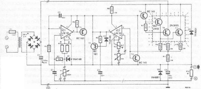
An 50v bench power supply can be made using electronic diagram below which is designed using LM10 op amp and 2n3055 transistors. This LM10 2n3055 50v bench power supply allows an output voltage regulation in a range between 0 and 50 volts and the output current can be limited to a maximum of 2A. Output voltage increases linearly with the amount of resistance potentiometer P1, while the current can be adjusted linear using potentiometer P3. Potentiometer P2 serves to regulate maximum output current (maximum value is 2A).
Saturday, March 30, 2013
Variable 5 to 20V DC Supply Rise
If you are looking for a low drop voltage regulator that can provide a power supply of 1A with an output voltage of between 5V and 20V DC, National Semiconductor LM2941 Low Dropout Adjustable Regulator is that you can pick to make use of. Its a typical dropout voltage of 0.5V which means that the input supply need only must be 0.5V DC over the desired output voltage. Its other features include internal short circuit current limit and reverse battery protection.
As shown in the schematic below, the regulator has five pins which consists of the ON/OFF control, Input Voltage, Output Voltage, Ground & Adjustable pins. ON/OFF is used for the purpose of switching on & off of the regulator. The capacitors C1 & E1 are to be placed as close as feasible to the regulator.

The output of the circuit can be varied by varying the worth of potentiometer VR1 from 5V DC to 20V DC. The input voltage is limited from five.5V DC to 30V DC. Resistor R1 must be greater than 1K. The worth of the VR1 that needs to be set is calculated from the formula given below:
If R1=1K, Vout = 5V, VR1 should be set to 2.9K ohm.
If R1=1K, Vout = 20V, VR1 should be set to 14.7K ohm

Monday, March 25, 2013
3V DC to 5V DC REGULATED POWER SUPPLY ELECTRONIC DIAGRAM

3V DC to 5V DC REGULATED POWER SUPPLY ELECTRONIC DIAGRAM
A 5V DC regulated output from 2 cells 3V DC batteries. The output current of the circuit is limited to 50mA. However, it still able to supply many microcontroller circuits. 3009 and 560R Resistor provide the 5V DC output, make up a voltage divider network.
Saturday, March 23, 2013
Adjustable Current Limit For Dual Power Supply
This current-limiting circuit, shown in this example as part of a small bench power supply, could in principle be used in conjunction with any dual-rail current source. The part of the circuit to the left of the diagram limits the current at the input to the dual voltage regulator (IC4 to IC7) so that it is safely protected against overload. The circuit shown produces outputs at ±15 V and ±5V. The voltage regulators at the outputs (7815/7805 and 7915/7905) need no further comment; but the current-limiting circuit itself, built around an LM317 and an LM337, is not quite so self-explanatory.
The upper LM317 (IC1) manages the current limiting function for the upper branch of the circuit. The clever part is the combination of the two resistors R1 and R3 between the output and the adjust input of the regulator. In the basic LM317 configuration in current-limiting mode (i.e.,as a constant current source), just one resistor is used here, across which the regulator maintains a constant voltage of 1.25 V. The current is thus limited to a value of 1.25 V/R. To obtain a maximum current of 1 A, for example, the formula tells us that the necessary resistor value is 1.25R.
Unfortunately it is not practical to try to build an adjustable dual-rail current-limited supply in this way, as stereo potentiometers with a value of 1.2R are extremely difficult, if not impossible, to obtain. We can solve the problem using the technique of dividing the resistor into two resistors. Only the resistor at the output of the LM317 (R1) serves for current sensing. The second resistor (R3) causes an additional voltage drop depending on an additional (and adjustable) current. When the sum of the two voltages reaches 1.25 V current limiting cuts in.
Circuit diagram:

This makes it possible to adjust the current limit smoothly using the current in the second resistor (R3). This can be done simultaneously in the positive and negative branches of the circuit, as the diagram shows. It would of course be wasteful to arrange for the current flowing in the second resistor to be of the same order of magnitude as the current in the main resistor. We therefore make the value of the second resistor considerably greater than that of the main one. If the main resistor (R1) has a value of 1.2R (giving a maximum current of 1 A), and the second resistor (R3) a value of 120R, the necessary voltage drop is achieved using an extra current of 10 ent limit will be 1 A.
For the negative branch of the circuit the LM337, along with resistors R2 (1.2r) and R5 (120R), performs the same functions. A further LM317 (IC3) is used to set the overall current limit point by controlling the additional current. The resistance used with this voltage regulator, wired as a current sink (R4 in series with P1) determines the additional current and therefore also the output current in both the negative and positive branches of the circuit. Since we also want the total resistance of R4 and P1 to be 120R, we use a value of 22R for R4 and 100R for P1 to give a wide adjustment range for the output current from a few milliamps to 1A.
The minimum input voltage for the circuit depends on the desired output voltage and maximum output current. The input to the 7815 should be at least 18 V. We should allow approximately a further 1.2 V + 2.2 V for the voltage drops across IC1 and R1. If we allow a total of 4V for the current limiting circuit in each branch, this means that the circuit as a whole should be supplied with at least ±22 V to produce well-regulated outputs at ±15 V and ±5V. If the symmetrical input voltage is to be provided using a single transformer winding, two diodes and two smoothing capacitors, it important to ensure that the capacitor values are sufficiently large, as there will be considerably more ripple than there would be with full-wave rectification.
Depending on the application, capacitors C6 to C9 at the outputs of the fixed voltage regulators can be electrolytics with a value of 4.7 µF or 10 µF. To improve stability, electrolytic capacitors can also be connected in parallel with C1, C2, C4 and C5.
More...
The upper LM317 (IC1) manages the current limiting function for the upper branch of the circuit. The clever part is the combination of the two resistors R1 and R3 between the output and the adjust input of the regulator. In the basic LM317 configuration in current-limiting mode (i.e.,as a constant current source), just one resistor is used here, across which the regulator maintains a constant voltage of 1.25 V. The current is thus limited to a value of 1.25 V/R. To obtain a maximum current of 1 A, for example, the formula tells us that the necessary resistor value is 1.25R.
Unfortunately it is not practical to try to build an adjustable dual-rail current-limited supply in this way, as stereo potentiometers with a value of 1.2R are extremely difficult, if not impossible, to obtain. We can solve the problem using the technique of dividing the resistor into two resistors. Only the resistor at the output of the LM317 (R1) serves for current sensing. The second resistor (R3) causes an additional voltage drop depending on an additional (and adjustable) current. When the sum of the two voltages reaches 1.25 V current limiting cuts in.
Circuit diagram:

Adjustable Current Limit For Dual Power Supply Circuit Diagram
This makes it possible to adjust the current limit smoothly using the current in the second resistor (R3). This can be done simultaneously in the positive and negative branches of the circuit, as the diagram shows. It would of course be wasteful to arrange for the current flowing in the second resistor to be of the same order of magnitude as the current in the main resistor. We therefore make the value of the second resistor considerably greater than that of the main one. If the main resistor (R1) has a value of 1.2R (giving a maximum current of 1 A), and the second resistor (R3) a value of 120R, the necessary voltage drop is achieved using an extra current of 10 ent limit will be 1 A.
For the negative branch of the circuit the LM337, along with resistors R2 (1.2r) and R5 (120R), performs the same functions. A further LM317 (IC3) is used to set the overall current limit point by controlling the additional current. The resistance used with this voltage regulator, wired as a current sink (R4 in series with P1) determines the additional current and therefore also the output current in both the negative and positive branches of the circuit. Since we also want the total resistance of R4 and P1 to be 120R, we use a value of 22R for R4 and 100R for P1 to give a wide adjustment range for the output current from a few milliamps to 1A.
The minimum input voltage for the circuit depends on the desired output voltage and maximum output current. The input to the 7815 should be at least 18 V. We should allow approximately a further 1.2 V + 2.2 V for the voltage drops across IC1 and R1. If we allow a total of 4V for the current limiting circuit in each branch, this means that the circuit as a whole should be supplied with at least ±22 V to produce well-regulated outputs at ±15 V and ±5V. If the symmetrical input voltage is to be provided using a single transformer winding, two diodes and two smoothing capacitors, it important to ensure that the capacitor values are sufficiently large, as there will be considerably more ripple than there would be with full-wave rectification.
Depending on the application, capacitors C6 to C9 at the outputs of the fixed voltage regulators can be electrolytics with a value of 4.7 µF or 10 µF. To improve stability, electrolytic capacitors can also be connected in parallel with C1, C2, C4 and C5.
Author: Malte Fischer
Copyright: Elektor Electronics
Copyright: Elektor Electronics
Subscribe to:
Posts (Atom)