Friday, May 31, 2013
Santomieri Systemsrj45 Wire Diagrams

Wiring Power Over Ethernet Wire 500ft Roll Cat5 Cable 1000ft Roll.
Santomieri Systems Cat 5 Rj45 Wire Diagrams.

Cat5 Av Matrix Switches Cat5 Audio Video Matrix Switch Solutions.

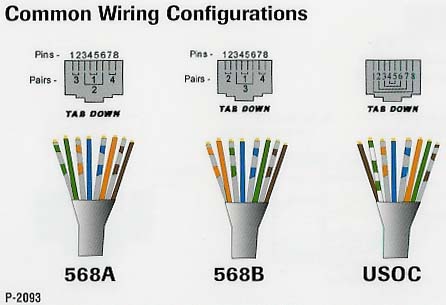
Standard Cat 5 Wiring Schemes Learning Scholarly Technologies.

On The Crimping Tool To Permanently Attach The Rj45 To The Cat5 Cable.

The Formal Cat5 Definition Reserves The Extra 4 Wires So.

Figure 4 Wiring Diagram For An Ethernet Crossover Cable.
There Are Two Wiring Standards For These Cables Called T 568a And T.

Category 5 Patch Cable In T568b Wiring.

Home Phone Wiring Diagram Using Cat5 Cable Here Source Scribd Com.
Friday, May 17, 2013
Mercury V8 Monterey 1963 Wiring Diagram Left Side Part
The schematic here is the wiring diagram of the 1963 Mercury V8 Monterey. The wiring diagram is divided in two different parts, here you can see the left side of the wiring diagram, and this is the Mercury V8 Monterey 1963 Wiring Diagram Right Side Part.
More...
 |
Mercury V8 Monterey 1963 Wiring Diagram Left Side Part |
As you can see, this wiring diagram is very clear, it shows many components and connections clearly. Some of the components you will see inside this left side part of the 1963 Mercury V8 Monterey wiring diagram are like: light switch, high beam indicator, oil pressure indicator, flasher, speedometer light, horn button, alternator indicator, etc.
Be sure to study both parts of the wiring diagrams first before attempting any wiring work like assembly or troubleshooting in your Mercury V8 Monterey. Save this wiring diagram for free in your PC.
Monday, May 13, 2013
Simple Water Level Indicator
This is the circuit diagram of a simple corrosion free water level indicator for home and industries.In fact the the level of any conductive non corrosive liquids can be measured using this circuit.The circuit is based on 5 transistor switches.Each transistor is switched on to drive the corresponding LED , when its base is supplied with current through the water through the electrode probes.
One electrode probe is (F) with 6V AC is placed at the bottom of tank.Next probes are placed step by step above the bottom probe.
When water is rising the the base of each transistor gets electrical connection to 6V AC through water and the corresponding probe.Which in turn makes the transistors conduct to glow LED and indicate the level of water.The ends of probes are connected to corresponding points in the circuit as shown in circuit diagram.Insulated Aluminum wires with end insulation removed will do for the probe.Arrange the probes in order on a PVC pipe according to the depth and immerse it in the tank.AC voltage is use to prevent electrolysis at the probes.So this setup will last really long.I guarantee at least a 2 years of maintenance free operation.That’s what I got and is still going.

Sunday, May 5, 2013
Simple 50V Bench Power Supply

An 50v bench power supply can be made using electronic diagram below which is designed using LM10 op amp and 2n3055 transistors. This LM10 2n3055 50v bench power supply allows an output voltage regulation in a range between 0 and 50 volts and the output current can be limited to a maximum of 2A. Output voltage increases linearly with the amount of resistance potentiometer P1, while the current can be adjusted linear using potentiometer P3. Potentiometer P2 serves to regulate maximum output current (maximum value is 2A).
Subscribe to:
Posts (Atom)