Showing posts with label emergency. Show all posts
Showing posts with label emergency. Show all posts
Monday, March 11, 2013
Cheap Emergency Light Circuit Diagram Using a Flashlight Bulb
Though its the world LEDs today, an ordinary flashlight bulb can also be considered a useful light emitting candidate especially because its much to configure than an LED.
The shown circuit diagram is quite simple to understand, a PNP transistor is used as the primary switching device.
A straight forward power supply provides the power to the circuit when mains is available.
As long as power is present, the transistor T1 remains positively biased and therefore remains switched OFF.
This inhibits battery power from entering the bulb and keeps it switched OFF.
The mains power is also utilized for charging the involved battery via the diode D2 and the current limiting resistor R1.
However, the moment AC mains fails, T1 is instantly forward biased, it conducts and allows the battery power to pass through it, which ultimately turns ON the bulb and the emergency light.
The entire unit may be adjusted inside a standard AC/DC adapter box and plugged IN directly in to an existing socket.
The bulb should be kept protruding outside the box so that the illumination reaches the external surrounding amply.
The moment AC mains fails,
Cheap Emergency Light Using a Flashlight Bulb Circuit Diagram
The shown circuit diagram is quite simple to understand, a PNP transistor is used as the primary switching device.
A straight forward power supply provides the power to the circuit when mains is available.
As long as power is present, the transistor T1 remains positively biased and therefore remains switched OFF.
This inhibits battery power from entering the bulb and keeps it switched OFF.
The mains power is also utilized for charging the involved battery via the diode D2 and the current limiting resistor R1.
However, the moment AC mains fails, T1 is instantly forward biased, it conducts and allows the battery power to pass through it, which ultimately turns ON the bulb and the emergency light.
The entire unit may be adjusted inside a standard AC/DC adapter box and plugged IN directly in to an existing socket.
The bulb should be kept protruding outside the box so that the illumination reaches the external surrounding amply.
The moment AC mains fails,
Cheap Emergency Light Using a Flashlight Bulb Circuit Diagram
Parts List
R1 = 470 Ohms,
R2 = 1K,
C2 = 100uF/25V,
Bulb = Small Flashlight Bulb,
Battery = 6V, Rechargeable Type,
Transformer = 0-9V, 500 mA


Thursday, March 7, 2013
Simple Emergency LED Light Circuit
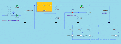 Simple Emergency LED Light Circuit
This emergency LED light is simple, inexpensive and easy to build. The circuit to the battery and when the main source is not available, such as brownouts, white LEDs turns on automatically.
Initially, the output voltage from 220V to 12V converter is fed to the input of LM317 regulator. Then, this voltage is regulated to 7.37V with 240 ohms and the combination of the resistance of 1.2K (see LM317 Calculator).
At this time, the battery is in charging mode and the transistor Q1 is off. LED serves two purposes, one is mainly to give us an idea of the battery is charging and the other is to ensure that Q1 is off.
During voltage drops, the transistor Q1 is on and supplies the current to 16 white LED of about 20 mA each, so a fully charged battery (6V/4.5Ah) may last up to 14 hours.
The charger has a built in over current control, but still protects the battery from overcharging and charging voltage is at 7.4V only.
Initially, the output voltage from 220V to 12V converter is fed to the input of LM317 regulator. Then, this voltage is regulated to 7.37V with 240 ohms and the combination of the resistance of 1.2K (see LM317 Calculator).
At this time, the battery is in charging mode and the transistor Q1 is off. LED serves two purposes, one is mainly to give us an idea of the battery is charging and the other is to ensure that Q1 is off.
During voltage drops, the transistor Q1 is on and supplies the current to 16 white LED of about 20 mA each, so a fully charged battery (6V/4.5Ah) may last up to 14 hours.
The charger has a built in over current control, but still protects the battery from overcharging and charging voltage is at 7.4V only.
Subscribe to:
Posts (Atom)