Showing posts with label using. Show all posts
Showing posts with label using. Show all posts
Tuesday, September 3, 2013
Mini Drill Speed Regulator Using Voltage Regulator
With an integrated voltage regulator connected reverse to a mini drill can be adjusted speed within certain limits so that it remain constant, independently of load. In the scheme presented below the electronic speed control is made by a voltage regulator, allowing use of motor which require a supply voltage from 2.5 V to 12 V at a maximum current absorbed by an 1A. Output voltage is determined by the ratio of resistances R1 and R2. Uout = (R1 + R2) Uc/R2. Uc is equal to -2.23 V for 79GU voltage regulator.
Mini Drill Speed Regulator Circuit diagram

Integrated controller is designed to keep constant the value of -2.23 V, the voltage from common terminal .
With the P2 potentiometer can be adjusted the degree of coupling (coupling the output voltage increases with increasing output current). Thus remains constant preset speed. Maximum voltage measured when the P2 is turned up must be about 20% lower than the maximum allowable voltage of the motor (if is not, the value of R1 should be reduced or enlarged accordingly). Voltage regulator is designed with thermal protection, but it must be mounted on a properly dimensioned radiator.
Mini Drill Speed Regulator Circuit diagram

With the P2 potentiometer can be adjusted the degree of coupling (coupling the output voltage increases with increasing output current). Thus remains constant preset speed. Maximum voltage measured when the P2 is turned up must be about 20% lower than the maximum allowable voltage of the motor (if is not, the value of R1 should be reduced or enlarged accordingly). Voltage regulator is designed with thermal protection, but it must be mounted on a properly dimensioned radiator.

Wednesday, March 27, 2013
LM741 Using Dry Cell Battery Charger Circuit
This is Dry Cell Battery Charger Circuit. That can use charger battery get that about 12 hour. When apply to power supply 9 volt the equipment that fix in the circuit use for size battery AA. If use the size C or D should devalue of Resistor RX down be 68ohm and should not lead battery come to serial while voltage in cell battery lower 1.6V.
The Comparator Circuit with (IC741) control Gate output from Pulse Oscillator at use the integrated circuit CMOS 4011 change Transistor that do infront charger battery until voltage tall 1.6V Comparator Circuit more make LED Flasher warn know for protect Charger battery expire. The next time is if friends have Dry Cell Battery that use be finished already , don’t abandon , try apply new again yes.
Circuit Diagram:
 LM741 Using Dry Cell Battery Charger Circuit Diagram
Source: Elecircuit
dry cell battery charger circuit
741 battery charger circuit
12 Volt battery using an LM741
aplikasi lm 741
ua741 use for battary chrger circuit
tubular battery charger using lm 741
lm741 ile şarj
fast charger for 12 volt tubular battery with display schematic diagram
dry cell charger soldering diagram
Load Acid Battery with LM741 Circuit Diagram
dry cell battery charger circuit
741 battery charger circuit
12 Volt battery using an LM741
aplikasi lm 741
ua741 use for battary chrger circuit
tubular battery charger using lm 741
lm741 ile şarj
fast charger for 12 volt tubular battery with display schematic diagram
dry cell charger soldering diagram
Load Acid Battery with LM741 Circuit Diagram
Thursday, March 21, 2013
Dual Power Amplifier Using TDA7293 MOSFET IC
As
readers will know, there are already several power amplifier projects,
two using IC power amps (aka power opamps). Both have been popular,
and this project is not designed to replace either of them. However, it
is significantly smaller than the others, so it makes building a
multiple amp unit somewhat easier because the space demand is much
lower. Its quite simple to include 4 amps (two boards) into a small
space, but be aware that good heatsinking is essential if you expect to
run these amps at significant power levels.

Photo of Completed P127 Board
The
TDA7293 IC uses a MOSFET power stage, where the others featured use
bipolar transistors. The main benefit of the MOSFET stage is that it
doesnt need such radical protection circuitry as a bipolar stage, so
unpleasant protection circuit artefacts are eliminated. There are no
apparent downsides to the TDA7293, although it was found that one batch
required a much higher voltage on the Standby and Mute pins than
specified, or the amps would not work. This is not a limitation, since
both are tied to the positive supply rail and are therefore disabled.
This particular project has been planned for a long time, but for some
reason I never got around to completing the board or the project
description. This is now rectified, and its ready to "rock and roll".
The board is very small - only 77 x 31mm, so getting it into tight
spaces is easy ... provided adequate heatsinking is available of course.
Description
The
TDA7293 has a bewildering number of options, even allowing you to add a
second power stage (in another IC) in parallel with the main one. This
improves power into low impedance loads, but is a rather expensive way
to get a relatively small power increase. It also features muting and
standby functions, although Ive elected not to use these.
The schematic is shown in Figure 1, and is based on the PCB version. All unnecessary functions have been disabled, so it functions as a perfectly normal power amplifier. While the board is designed to take two TDA7293 ICs, it can naturally be operated with only one, and the PCB is small enough so that this is not an inconvenience. A LED is included to indicate that power is available, and because of the low current this will typically be a high brightness type.
The schematic is shown in Figure 1, and is based on the PCB version. All unnecessary functions have been disabled, so it functions as a perfectly normal power amplifier. While the board is designed to take two TDA7293 ICs, it can naturally be operated with only one, and the PCB is small enough so that this is not an inconvenience. A LED is included to indicate that power is available, and because of the low current this will typically be a high brightness type.

Figure 1 - Schematic of Power Amplifier (One Channel Shown)
The
IC has been shown in the same format thats shown in the data sheet,
but has been cleaned up for publication here. Since there are two amps
on the board, there are two of most of the things shown, other than the
power supply bypass caps and LED "Power Good" indicator. These ICs are
extremely reliable (as are most power amp ICs), and to reduce the PCB
size as much as possible, fuse clips and fuses have not been included.
Instead, there are fusible tracks on the board that will fail if there
is a catastrophic fault. While this is not an extremely reliable fuse,
the purpose is to prevent power transformer failure, not to protect the
amplifiers or PCB. I normally use a gain of 23 (27dB) for all
amplifiers, and the TDA7293 is specified for a minimum gain of 26dB,
below which it may oscillate. Although this is only a small margin,
tests so far indicate that the amp is completely stable. If you wish,
you may increase the gain to 28 (29dB) to give a bit more safety margin.
To do this, just change the input and feedback resistors (R3A/B and
R4A/B) from 22k to 27k.
The circuit is
conventional, and is very simple because all additional internal
functions are unused. The LED is optional, and if you dont think youll
need it, it may be omitted, along with series resistor R3. All
connections can be made with plugs and sockets, or hard wired. In most
cases, I expect that hard wiring will be the most common, as the
connectors are a pain to wire, and add unnecessary cost as well as
reduce reliability. The TDA7293 specifications might lead you to
believe that it can use supply voltages of up to ±50V. With zero input
signal (and therefore no output) it might, but I dont recommend
anything greater than ±35V if 4 ohm loads are expected, although ±42V
will be fine if you can provide good heatsinking. In general, the lower
supply voltage is more than acceptable for 99% of all applications, and
higher voltages should not be used unless there is no choice.
Naturally, if you can afford to lose a few ICs to experiments, then go
for the 42V supplies (obtained from a 30+30V transformer).
Construction
Because
of the pin spacings, these ICs are extremely awkward to use without a
PCB. Consequently, I recommend that you use the ESP board because it
makes building the amplifier very simple. The PCBs are double sided with
plated-through holes, so are very unforgiving of mistakes unless you
have a good solder sucker. The best way to remove parts from a double
sided board is to cut the pins off the component, then remove each pin
fragment individually. This is obviously not something youd wish to do
if a power amp IC were installed incorrectly, since it will be unusable
afterwards.

Figure 2 - TDA7293V Pinouts
The
diagram above shows the pinouts for the TDA7293V (the "V" means
vertical mounting). Soldering the ICs must be left until last. Mount the
ICs on your heatsink temporarily, and slide the PCB over the pins.
Make sure that all pins go through their holes, and that there is no
strain on the ICs that may try to left the edge off the heatsink. When
ICs and PCB are straight and aligned, carefully solder at least 4 pins
on each IC to hold them in place. The remaining pins can then be
soldered. Remember, if you mess up the alignment at this point in
construction, it can be extremely difficult to fix, so take your time
to ensure there are no mistakes. This amplifier must not be connected
to a preamp that does not have an output coupling capacitor. Even
though there is a cap in the feedback circuit, it can still pass DC
because there is no input cap on the PCB. I normally include an input
cap, but the goal of this board was to allow it to fit into the
smallest space possible, and the available board space is not enough to
include another capacitor. A volume control (typically 10k log/ audio
taper) may be connected in the input circuit if desired.
Note
that the metal tab of the TDA7293 is connected to the -Ve supply, so
must be insulated from the heatsink. The more care you take with the
mounting arrangement, the better. While you can use a screw through an
insulating bush and a piece of mica to insulate the tab, a better
alternative is to use a clamping bar of some kind. How you go about
this depends a lot on your home workshop tools and abilities, but one
arrangement Ive found highly satisfactory is a suitable length of
6.25mm square solid steel bar. This is very strong, and allows good
pressure on the mica (or Kapton) for maximum heat transfer. Naturally,
heatsink compound is absolutely essential. Do not be tempted to use
silicone insulation washers unless you are using the amp at very low
supply voltages (no more than ±25V). Its thermal transfer
characteristics are not good enough to allow the amp to produce more
than about 10 - 20W of music, and even that can be taxing for silicone
washers. The amp will shut down if it overheats, but that curtails ones
listening enjoyment until it cools down again.
Power Supply
A
suitable power supply is shown below, and is completely unremarkable
in all respects. The transformer may be a conventional (E-I) laminated
type or a toroid. The latter has the advantage of lower leakage flux,
so will tend to inject less noise into the chassis and wiring.
Conventional transformers are usually perfectly alright though, provided
you take care with the mounting location. The bridge rectifier should
be a 35A 400V type, as they are cheap, readily available and extremely
rugged. Electrolytic capacitors should be rated at 50V. The cap
connected across the transformer secondary (C4) should be rated at 275V
AC (X Class), although a 630V DC cap will also work. This capacitor
reduces "conducted emissions", namely the switching transients created
by the diodes that are coupled through the transformer onto the mains
supply. The power supply will work without this cap, and will most
likely pass CE and C-Tick tests as well, but for the small added cost
you have a bit of extra peace of mind as regards mains noise.

Figure 3 - Suggested Power Supply
The
supply shown includes a "loop breaker", which is intended to prevent
earth/ ground loops to prevent hum when systems are interconnected.
Please be aware that it may not be legal to install this circuit in some
countries. The diodes must be high current types - preferably rated at
no less than 3A (1N5401 or similar). The loop breaker works by
allowing you to have the chassis earthed as required in most countries,
but lets the internal electronics "float", isolated from the mains
earth by the 10 ohm resistor. RF noise is bypassed by the 100nF cap,
and if a primary to secondary fault develops in the transformer, the
fault current will be bypassed to earth via the diodes. If the fault
persists and the internal fuse (or main power circuit breaker) hasnt
opened, one or both diodes will fail. Semiconductor devices fail
short-circuit, so fault current is connected directly to safety earth.
Be
very careful when first applying mains power to the supply. Check all
wiring thoroughly, verify that all mains connections are protected from
accidental contact. If available, use a Variac, otherwise use a
standard 100W incandescent lamp in series with the mains. This will
limit the current to a safe value if there is a major fault. When the
loop breaker is used, all input and output connectors must be insulated
from the chassis, or the loop breaker is bypassed and will do nothing
useful. The body of a level pot (if used) can be connected to chassis,
because the pot internals are insulated from the body, mounting thread
and shaft.
Note that the DC ground for
the amplifiers must come from the physical centre tap between the two
filter caps. This should be a very solid connection (heavy gauge wire
or a copper plate), with the transformer centre tap connected to one
side, and the amplifier earth connections from the other. DC must be
taken from the capacitors - never from the bridge rectifier. The order
of the fuse and power switch is arbitrary - they can be in any order,
and in many cases the order is determined by the physical wiring of the
IEC connector if a fused type is used. With a fused IEC connector, the
fuse is before the switch and it cannot be removed while the mains
lead is inserted.
I have shown a 2A
slow-blow fuse, but this depends on the size and type of transformer
and your mains supply voltage. Some manufacturers give a recommended
fuse rating, others dont. The fuse shown is suitable for a 150VA
transformer at 230V AC, and is deliberately oversized to ensure that it
will not be subject to nuisance blowing due to transformer inrush
current. A 2A fuse will fail almost instantly if there is a major
fault. Make sure that the mains earth (ground) is securely connected to
guarantee a low resistance connection that cannot loosen or come free
under any circumstances. The accepted method varies from one country to
the next, and the earth connection must be made to the standards that
apply in your country.
WARNING: This power supply circuit requires experience with mains wiring. Do not attempt construction unless experienced, capable and suitably qualified if this is a requirement where you live. Death or serious injury may result from incorrect wiring.
Never attempt to operate the amplifier without the TDA7293 ICs attached to a heatsink!
Connect to a suitable power supply - remember that the supply earth (ground) must be connected! When powering up for the first time, use 100 ohm 5W "safety" resistors in series with each supply to limit the current if you have made a mistake in the wiring. If available, use a variable bench supply - you dont need much current to test operation, and around 500mA is more than enough. If using a current limited bench supply, the safety resistors can be omitted. Do not connect a speaker to the amplifier at this stage!
Connect to a suitable power supply - remember that the supply earth (ground) must be connected! When powering up for the first time, use 100 ohm 5W "safety" resistors in series with each supply to limit the current if you have made a mistake in the wiring. If available, use a variable bench supply - you dont need much current to test operation, and around 500mA is more than enough. If using a current limited bench supply, the safety resistors can be omitted. Do not connect a speaker to the amplifier at this stage!
If using a
normal power supply for the amp tests, apply power (±35V via the safety
resistors) and verify that the current is no more than 60mA or so -
about 6V across each 100 ohm resistor. No load current can vary, so
dont panic if you measure a little more or less. Verify that the DC
voltage at both outputs is less than 100mV. Using another 100 ohm
resistor in series with a small speaker, or an oscilloscope, apply a
sinewave signal at about 400Hz to the input and watch (or listen) for
signal. The signal level needs to be adjusted to ensure the amp isnt
clipping, and the waveform should be clean, with no evidence of
parasitic oscillation or audible distortion. If everything tests out as
described, wire the amplifier directly to the power supply and finish
off any internal wiring in the amp. Once complete, its ready to use.
Sunday, March 17, 2013
Make a 6v 4ah Automatic Battery Charger Circuit without Using a Relay

this is diagram a 6V 4.5 AH battery charger circuit which is able to charge 6V 4.5 AH lead acid batteries. The schematic is very simple and using only few components. IC LM317T is the heart of the circuit. The circuit is automatic so when the battery will become full charge it will stop charging. These type of circuits are very useful for solar garden light and can also be used in other circuits like emergency led lamp etc. Use transformer 230 AC to 9V / 500mA.
Wednesday, March 13, 2013
Designing Circuits using Eagle CAD
Submitted by Mr.Judith
Eagle CAD is a Professional PCB design package from the German company CadSoft. It offers an array of licenses, some of which allow individuals to use the package virtually free of charge. The learning curve may be a bit steep, but then Computer Aided Drafting is hardly simple, and most CAD packages have steep learning curves.
Eagle CAD is a Professional PCB design package from the German company CadSoft. It offers an array of licenses, some of which allow individuals to use the package virtually free of charge. The learning curve may be a bit steep, but then Computer Aided Drafting is hardly simple, and most CAD packages have steep learning curves.
The CAD package runs under Windows, Linux and OS X, ensuring complete compatibility. There is an online forum, which has an active support from the user members as well as CadSoft itself..
Many people find it difficult to locate components in the official libraries. Although the libraries are extensive, they are somewhat old-fashioned and the nomenclature is more suited to the component packages (with leads) as compared to the more common lead-less SMD packages often distributed these days.
To add components to a schematic, you have to use the ADD dialog. This is available when you click the ADD button in the GUI menu. You must be careful of the DROP button in the ADD dialog. This is not a button to drop the part into the schematic. It actually drops the particular library from the available libraries. If you have disabled a library in this way, you can re-enable it at startup by expanding the Library and clicking the dot beside the disabled library.
Once you have finished with the ADD dialog, the part attaches itself to your mouse pointer, and you can place it at the desired location on the drawing page, when you click the left mouse button. When you click the right mouse button, the part rotates 90 degrees. Pressing the middle button mirrors the part, which is also useful at times.
Selecting generic resistors and capacitors pose the biggest challenge to a newcomer to Eagle. Resistors are classified in the library in two different ways as the R-US (the zigzag line type, mostly used in the US), and as the R-EU style (the rectangle type, mostly used in Europe). The package options are as WWLL/SS. Here, WW represents the body width, LL represents the body length, and SS represents the hole spacing. The numbers are all truncated millimeters. Thus, R-US_0207/10 means a resistor with 2.54mm diameter, 7.62mm length and 10.16mm hole spacing. For vertically mounted resistors, the designation will become R-US_0207/10V.
Selecting a capacitor is even more complex than selecting a resistor. This is mostly because capacitors come in a wider variety and have different shapes. The two major forms are still the C-EU and the C-US in the library. The standard package nomenclature for designating a capacitor follows SSS-WWWXLLL, where SSS represents the lead spacing, WWW represents the body width, and LLL represents the body length.
Polarized capacitorsare classified in the library as CPOL-EU or CPOL-US, and the package nomenclature follows TSSS-DD, with T representing the type (TT for tantalum and E for electrolytic), DD representing the diameter (mainly for radial types) and SSS again representing the lead spacing.
Monday, March 11, 2013
Cheap Emergency Light Circuit Diagram Using a Flashlight Bulb
Though its the world LEDs today, an ordinary flashlight bulb can also be considered a useful light emitting candidate especially because its much to configure than an LED.
The shown circuit diagram is quite simple to understand, a PNP transistor is used as the primary switching device.
A straight forward power supply provides the power to the circuit when mains is available.
As long as power is present, the transistor T1 remains positively biased and therefore remains switched OFF.
This inhibits battery power from entering the bulb and keeps it switched OFF.
The mains power is also utilized for charging the involved battery via the diode D2 and the current limiting resistor R1.
However, the moment AC mains fails, T1 is instantly forward biased, it conducts and allows the battery power to pass through it, which ultimately turns ON the bulb and the emergency light.
The entire unit may be adjusted inside a standard AC/DC adapter box and plugged IN directly in to an existing socket.
The bulb should be kept protruding outside the box so that the illumination reaches the external surrounding amply.
The moment AC mains fails,
Cheap Emergency Light Using a Flashlight Bulb Circuit Diagram
The shown circuit diagram is quite simple to understand, a PNP transistor is used as the primary switching device.
A straight forward power supply provides the power to the circuit when mains is available.
As long as power is present, the transistor T1 remains positively biased and therefore remains switched OFF.
This inhibits battery power from entering the bulb and keeps it switched OFF.
The mains power is also utilized for charging the involved battery via the diode D2 and the current limiting resistor R1.
However, the moment AC mains fails, T1 is instantly forward biased, it conducts and allows the battery power to pass through it, which ultimately turns ON the bulb and the emergency light.
The entire unit may be adjusted inside a standard AC/DC adapter box and plugged IN directly in to an existing socket.
The bulb should be kept protruding outside the box so that the illumination reaches the external surrounding amply.
The moment AC mains fails,
Cheap Emergency Light Using a Flashlight Bulb Circuit Diagram
Parts List
R1 = 470 Ohms,
R2 = 1K,
C2 = 100uF/25V,
Bulb = Small Flashlight Bulb,
Battery = 6V, Rechargeable Type,
Transformer = 0-9V, 500 mA

Friday, March 8, 2013
Regulator 5 volt using IC 7805
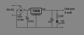 Regulator 5 volt using IC 7805 Circuit
 Although the 7805 were designed primarily for fixed output voltage (5V), it is possible to use external components for voltage DC output: 5V, 6V, 8V, 9V, 10V, 12V, 15V, 18V, 20V, 24 . Note that the input voltage, of course, be greater than the required output voltage, so you can down-regulate

Features IC regulator 7805
• Output Current up to 1A
• Output Voltages of 5 Volt
• Thermal Overload Protection
• Short Circuit Protection
• Output Transistor Safe Operating Area Protection
Data max IC 7805
Input Voltage........................................ 35
Thermal Resistance Junction-Cases (TO-220)40......... 5 °C/W
Thermal Resistance Junction-Air (TO-220)............. 65 °C/W
Operating Temperature Range (KA78XX/A/R)............. 0 ~ +125 °C
Storage Temperature Range............................ -65 ~ +150 °C.
Subscribe to:
Posts (Atom)